|
We're your one stop scale model
train shop!

Totally Wired Telephone Poles
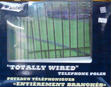
The "Totally Wired Telephone Poles" from Rapido Trains have arrived. Above is a picture of
the box.
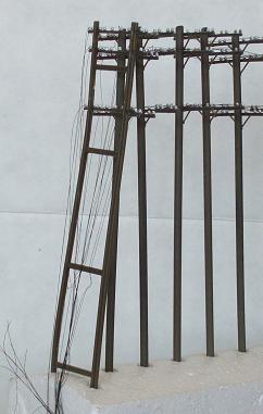
The box contains; 11 telephone Poles, a left wire keeper assembly, a right 'H' Pole assembly
and a support for the wire reels.
As well there is a spare pole with three cross arms. This needs to be assembled.
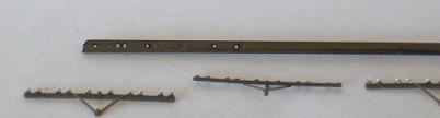
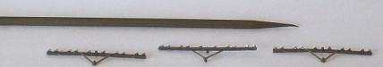
Note that the mounting holes for the cross arm assemblies have been highlighted.
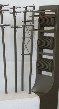
There are 17 wires strung along the poles; two wires on the top cross arms, eight wires on
the middle cross arms and seven wires on the bottom cross arms.
Preparation for Installation
Figure out the pole spacing and drill holes for the bottoms of the poles. Be careful of the spacing
for the right 'H' Pole assembly. With the pointed ends to the poles you could just push them into
a soft scenery base ( Styrofoam ) but it would be better to drill holes.
Assemble the spare pole. You need to use this to replace the left wire keeper assembly.
- Jason tells me that this is a spare pole and the left wire keeper assembly is mean to be attached
to a building. Oops, that means my entire set of poles is backwards for my intended use. I guess I
will have to re string the whole set to get the 'H' pole assembly on the left end. That can wait
until the Telephone Exchange Building is built (see later).
Threading the Wires.
You need to replace the left wire keeper with the spare pole. To do this I move the left keeper
assembly back one hole (front leg is in the rear hole) and put the spare pole in the front hole.
Separate the bundle of wires taped to the left end of the holder. You will find three bundles of
wires; one of two wires (top cross arm), one of eight wires (middle cross arm) and one of seven
wires (bottom cross arm).
 Starting with the top bundle, untie the knot (if you can) or cut it off. Then using fine tweezers,
good light and magnification (I use MagEyes - lighter than an Opti-Visor) thread the wires
through the drilled insulators. I start from the back and work forward. When all the wires are
threaded through the insulators gather the ends into a small bundle and super glue them together.
Starting with the top bundle, untie the knot (if you can) or cut it off. Then using fine tweezers,
good light and magnification (I use MagEyes - lighter than an Opti-Visor) thread the wires
through the drilled insulators. I start from the back and work forward. When all the wires are
threaded through the insulators gather the ends into a small bundle and super glue them together.
Note that this will be easier to do if you unreel a bit of the wire.
Repeat the same process with the middle cross arm and then the bottom cross arm.
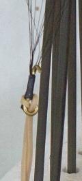
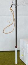
When all the wires are threaded through glue the three bundles of wires together into one bundle.
This will eventually be glued somewhere to anchor the ends of the wires. As I am going to be
using these on my HO modules I added a wire loop. I used heat shrink tubing and super glue to
attach the wires to the wire loop. I threaded an elastic band through this loop and will anchor it to
a hook behind a bush to keep a light tension on the wires.
Installation
After you have the holes drilled, the spare pole installed, and figured out how to anchor the end
of the wires you are almost ready.
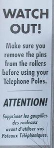
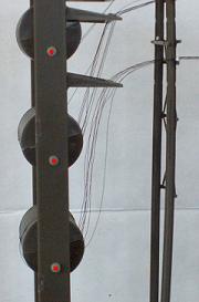
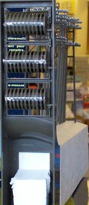
There is one important step omitted from the instructions. You need to remove the reel locking
pins before attempting to install the poles. It is important enough that they have put a label on the
inside of both of the box end flaps. Note on the image I have highlighted the pins in red. As well
as removing the pins you also have to remove a piece of clear tape on each set of reels.
Changes
All of the Insulators are the same white colour. Although it was a long time ago and I suspect
that there are few that remember installing pole lines like this I would not be surprised if they
used all the same type of insulators when the lines were new. Over time additions or
replacements could be of a different type. You could simulate this by painting random ones a
different colour (brown or green) or perhaps simulate the addition of more lines by making a
whole set of insulators along the whole line of poles a different colour.
All of the cross arms are on the same side of the poles. They should (in some cases) be on
alternate sides of the poles with pairs of them facing each other. To do this would require
removing and re threading all the wires. Not fun - This has turned out to be easier than I
thought. Patience, magnification, and good light are the key.
There are too many wires for some installations. It would be easy to remove a cross arm and the
attendant wires. As well it would be easy to remove extra insulators.
For extra detail the pairs of lines need to be "frogged"( Wires Transposed ). This involved
crossing pairs of lines every mile or so. This was done in one of two ways. There was a mid span
casting ( This would be a nice super detail but I don't know how you would make it.) and castings
used on the cross arms. (See later).
Modular Use
 |
As noted before I intend to try a set on my HO scale modules at the next modular setup (this
coming weekend Sept 13-14). It should be easy to install them. Taking them up again without
making a mess of the wires will no doubt be a bigger issue. To prepare them for installation I
have added (glued on) styrene tube bases to fit the existing holes in my modules.
After this weekend I will post a few pictures and report on how well they worked and how big a
mess I made trying to wind up the wires. |
|
Saturday September 13, 2008.
Well the installation last night did not go as well as in the video. I let a bit of slack accumulate
around the wire reels and they tangled up. I eventually did get the whole set out but I have a mess
to clean up.
Currently I am thinking about replacing the existing wire reels with sewing machine bobbins.
They will have smoother edges than the current reels and should be less prone to tangle. It is
clear that a bit of tension needs to be kept on all the reels to reduce the possibility of tangles.
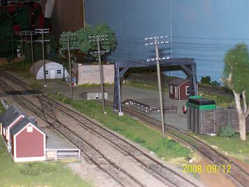
The picture here was taken last night (Friday the 12th.). It shows some of the set of poles on my
first set of modules.
Well the poles looked OK (even with the slack lines). I did not use the existing reels to wind up
the wires as I had a tangled mess around the old reels. I used a piece of cardboard (see later
picture) to wind the wire bundle around for transport. This worked quite well.
|
|
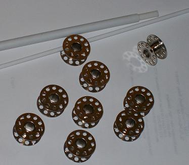
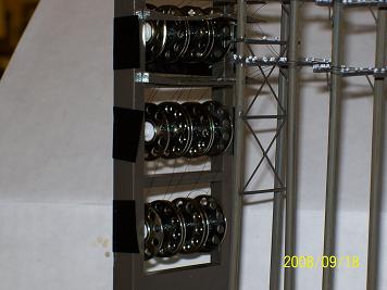
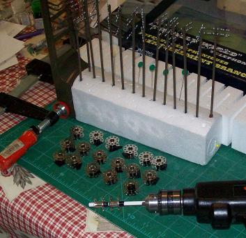
Monday evening I made new reels using sewing machine bobbins (12 for a buck at the Dollar
Store). Due to the size of the bobbins I was only able to get three per level.
The bobbins need a new axle assembly. I used three sizes of Evergreen Styrene to make the axle
assembly.
The innermost axle is made of #224 1/8" tubing. It need to be cut long enough to fit over the
posts on the reel holder assembly but not so long as to make it difficult to install. The tubing
needs to be reamed out a bit to fit over the pons.
The bobbins fit over a two part assembly. The inner axle is made from #226 3/16" tubing. Out
side of this I used #28 1/4" tubing. The 1/4" tubing is a bit too large to fit inside the bobbins and
a bit loose on the 3/16" Tubing. To fix this I cut four slots in the 1/4" tubing. Then I glued the
1/4" tubing to the 3/16" tubing. Test this with the bobbins. The should be a snug fit but you
should still be able to run them. This will allow you to adjust the slack on individual pairs of
lines.
|
|
I used a bit of electrical tape to attach the wires to the bobbin and carefully wound the wires up.
As there are only nine bobbin wire reels all but one bobbin have two wires on them. This works
well with no tangles.
I wound one bobbin at a time and them placed it on the axle. When all three bobbins were on one
axle I put them on the rack and applied a piece of electrical tape to keep the bobbins from
turning. After all three levels of bobbins were on the rack I wound up the wires. This worked
much better than the plastic reels.
|
|
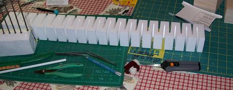
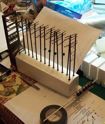
Note: A good holder for the poles is apiece of Woodland Scenics Foam Subterrain. The
notches held my pole bases perfectly. An 'F' clamp and the foam and on the telephone pole holder
helped stabilize things while I was working on them.
|
Now I am ready for the next show (Victoria on the 21st). More info next week on how well that
went.
To Do
- As mentioned above the poles are strung the wrong way around for where I want to put them
on my modules. I need the H Pole assembly on the left and the wire termination on the right.
- Painting insulators. Currently I have painted one pair of insulators on each pole green to
simulate an added pair. When I rewire all the poles I will paint all the insulators on the lower
cross arm brown to represent a later addition. This would also be a good time to touch up the
poles - change the colour a bit on some of them.
- I am going to (carefully) remove some of the unused insulators.
-
Using the removed insulators I am going to try and make one of the wire Transposition
assemblies.
It took a bit of digging but I found a few references for Transposition.
The UPRR POLE LINE - ROY
UTAH - AUGUST 2003 web site has a few good pictures of transposition. See figures 12
thru 16. Figure 15 is especially interesting as it explains how often they transpose the wires.
See a CD 1049 mid span
bracket. This would be fun to build.
I found a Canadian Patent for a cross arm bracket. This
would be easy to build. There is another Patent here.
This would be harder to build. Either would be a nice detail.
-
I think a bird or two perched on top of one of the poles would be a good detail. Preiser
makes a set of wild birds. One or two of those will do.
-
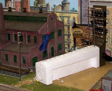
The Telegraph lines need a building to terminate in. I have a space currently occupied by
an oil dealer. This model is a few years old and shows the wear and tear caused by transporting
the model to shows. This will be replaced by a three story brick building. I do not know yet if it
will be made from DPM or Walthers modular components or something else.
- The bottom floor will have a loading dock serving 'Pinsky's Poultry Products' (at last a
destination for those Ambroid Chicken cars) makers of 'Extra Virgin Schmaltz'.
- The second floor will be a mattress and pillow making company - a destination for all those
feathers. No idea of the name yet but if I can find out what company Little Abner worked at as a
mattress tester that would do. There may be an herbalist in the back (Agnes Nutter's Potions and
Prophecies),
- The third floor will have the "Valley Telephone & Telegraph Company' - Our Motto: 'Our
Customers are Connected to the World because they are 'Totally Wired'.
- Tentatively the building will be called the 'Shron' Block.
The Victoria, B.C. Show
|
 |
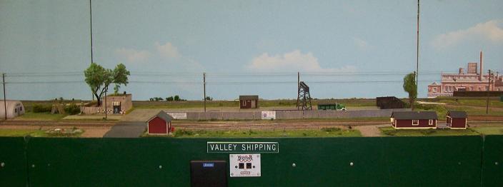
The pole line looked good. Installation off of the new bobbin reels went well. I need to
adjust two of the pole positions (done at the end of the show) to straighten out the pole line.
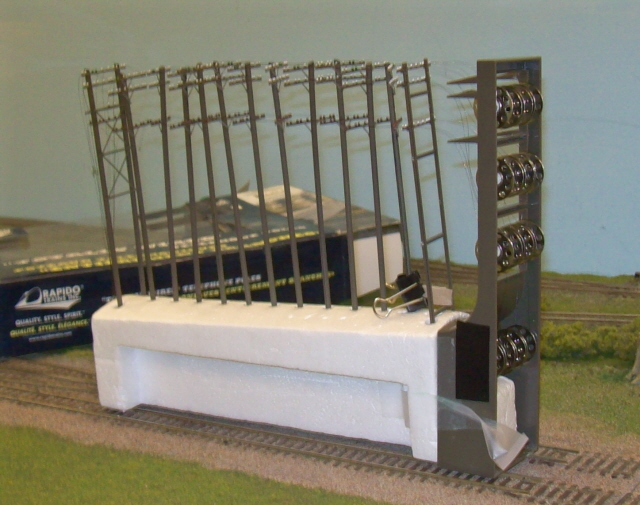
This was the way the wires were terminated. The blue clamp was to keep equal tension on all the
lines (I carefully pulled on all of the wires and until they all had equal tension on them then
added the clamp). Later a piece of black landscape cloth was used to hide the styrofoam.
|
|
The wires did not wind up well so the backup method was used. I let the reels run loose and
the wires tangled. The reels need some drag on them to stop this. Also some of the wires in the
alignment brackets do not line up well with the reels. Something to be fixed when the wires are
re strung.
|
Restringing the wires
|
As mentioned earlier I intended to rearrange the poles. Now is the time. The total time to do
this was about four hours including unstringing the wires, touch up painting the poles, and re
stringing the wires.
|
|
When you finish removing the wires you end up with an empty set of poles and seventeen spools
of removed wire.
I removed the wires one pair at a time (one new wire bobbins worth). I used an electric screw
driver to unwind the wires. Don't use a Dremel (or equivalent), you can't slow it down enough
and will most likely damage something when you come to the end of a wire.
With the wires removed I rearranged the poles (H Pole assembly on the end and the H Keeper
assembly on the reel end). I repainted the lower insulators brown. This worked but causes a
problem. On a white insulator you can see the wire hole clearly. On a brown insulator, even with
magnification, it is very hard to see.
This was also the time to paint the cross arm support braces light grey to represent galvanized
metal.
|
|
I installed three bobbins on their axle and added pieces on the end to reduce side play and add a
bit of drag to the reels.
Starting on the bottom cross arm at the back I strung each wire.
Put the wire reel on the axle to the right and using tweezers, good light and magnification,
carefully thread the wire through each insulator. When you get to the bobbin assembly thread it
through the wire alignment arm and pull about three inches through
String the second wire for that bobbin. Even the ends of the wires up and using a piece of tape,
tape the ends to their keeper bobbin.
Then on to wire three, four, five and six. When all the wires on one cross arm have been taped to
their bobbins take up the slack on the right reels and start winding the left reels. This takes some
time to wind up 15 feet of wire (there is supposed to be sixteen feet but I have been losing a bit
every time I redo things)..
Take a break then do the middle cross arm wires. Take another break then do the top cross arm
wires.
I used this opportunity to change the location of the wires. I now have six wires on the bottom
cross arm, two on each outside pair of insulators and on pair on the insulators closest to the
poles. The middle cross arm now has five wires, two on each outside pair of insulators and one
up the middle. The top cross arm now has six wires, again two each on the outside pair of
insulators and the last pair on the insulators that were painted green.
|
|
I still have to add the birds to the poles (when they arrive).
The Telephone Exchange Building needs to be built yet. I am acquiring DPM components to
build the three story building.
This should be ready for the next setup at the Chilliwack show in October 2008.
The poles were ready for Chilliwack but did not pack up very well.
They were used again at Trains 2008. They worked well but he pack up was a disaster!
The poles were unstrung after that show and the re stringing started. The poles sat unused and
partially re strung for a long time. The Rapido Trains display in the store June 28, 2011 inspired
me to finish restringing them. See the Rapido Visit page
for pictures of the poles in use. Currently I only have 13 wires strung, each on their own bobbin.
The bobbins are on four levels, three on each of the original upper three levels and four more on
a new lower level. This still has problems on rolling the wire up and keeping the tension on the
lines. I will add individual drags to each of the bobbins and better wire guides for the lower level
wires. I would like to add more wires but the bobbins only come in one size. I am going to find
plastic bobbins and try to narrow them.
Here is a picture of the new MK 3 holder.
|
Bill Dixon
Back to HO products
New September 12, 2008. - updated: July 2, 2011
www.central-hobbies.com
Central Hobbies
2825 Grandview Hwy, Vancouver, BC,
Canada, V5M 2E1
Phone 1-604-431-0771, Fax
1-604-431-9855
Orders Only 1-888-7TRAINS
(1-888-787-2467)
Page and Contents Copyright Central Hobbies 2014
|
![[Button Bar]](../images/bb_products.gif)